In September, I was promised additional photographs of the 1932 Watanabe rifle, though they have not yet arrived. Nevertheless, given the research already completed, there is more than enough new material to create a dedicated thread. Special and sincere thanks go to Adam Nowak for kindly providing the archival photographs and museum data!
1932 Watanabe Semi-Automatic Rifle
Historical Background and Technical Description
Research and development of automatic firearms at the private metallurgical company Nippon Special Steel Co., Ltd. (Nippon Tokushukō / 日本特殊鋼株式会社), founded by metallurgical engineer Saburō Watanabe, began in 1929 (Shōwa 4). In 1932 (Shōwa 7), the company expanded its toolmaking and repair workshops, establishing an experimental production line for automatic rifles and machine guns.
On June 3, 1932, Saburō Watanabe filed a patent application titled “Improvement in Automatic Rifles” (published on September 20, 1933, under Publication No. 4066; Patent No. 104319 was granted on December 23, 1933). Subsequent developments by the company led to the Type Hei trials semi-automatic rifle and the 1938 ultra-light machine gun prototype. In August 1945, prior to handing over the Haneda plant to the American occupation authorities, all military technical documentation and blueprints were burned overnight by plant personnel.
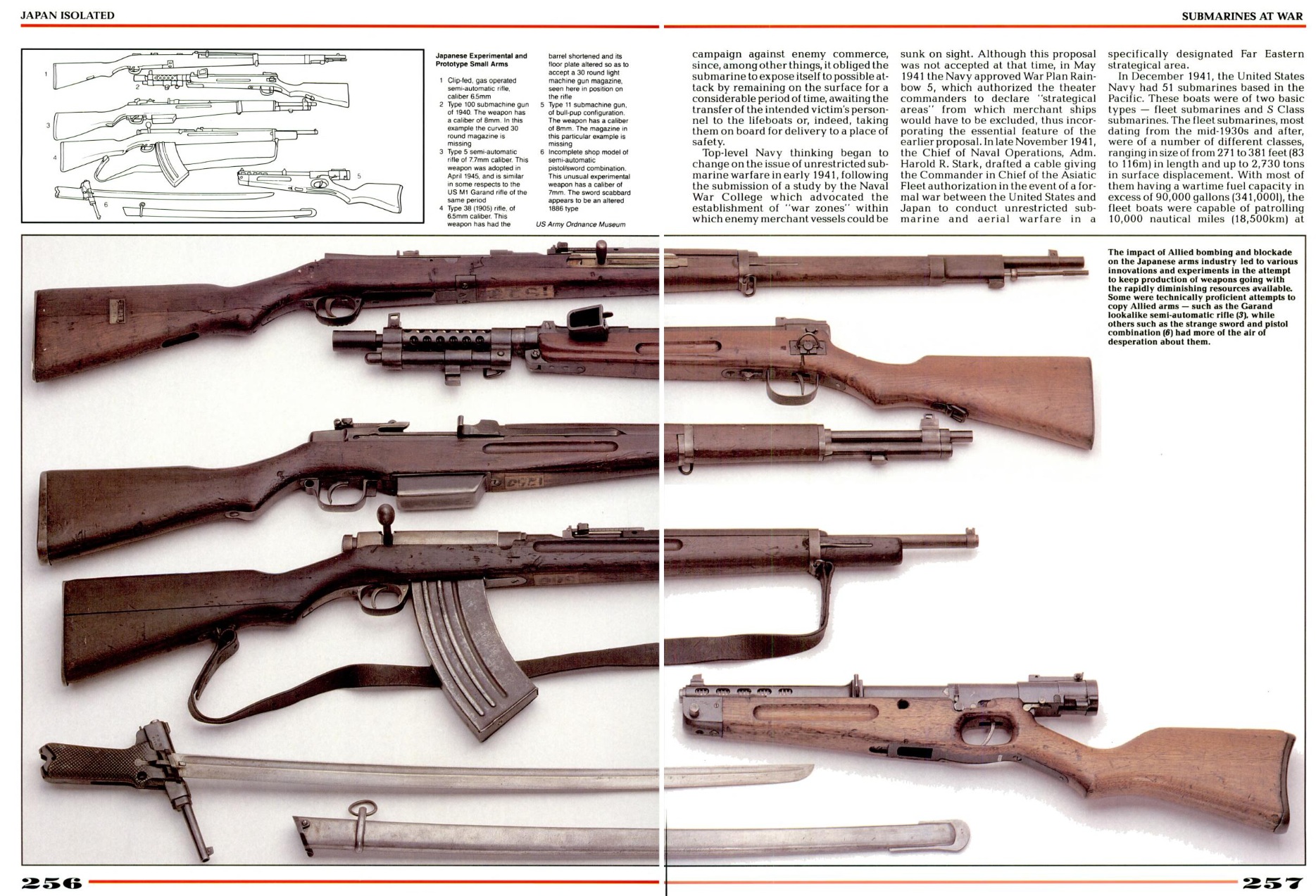
For decades, the only surviving physical example of the 1932 rifle, held in the collection of the U.S. Army Ordnance Training Support Facility, remained unattributed. In Western literature (notably in War in the Pacific: Pearl Harbor to Tokyo Bay, pp. 256–257), it was listed merely as an unidentified experimental 6.5mm rifle (“Item #1: Clip-fed, gas operated semi-automatic rifle, caliber 6.5mm”). Cross-referencing photographs of specimen No. 75269—kindly provided by museum curator Adam C. Nowak—with the drawings of Japanese Patent No. 104319 made it possible to definitively attribute the rifle to Saburō Watanabe and reconstruct its internal mechanics.
A metal plaque affixed to the buttstock bears the inscription 造兵學教室 (Zōheigaku Kyōshitsu — “Department of Ordnance / Ordnance Classroom”), indicating that the rifle was transferred as an instructional and research aid to a specialized military-engineering faculty. According to the U.S. museum’s internal records, the rifle was captured from Chinese Communist forces during the Korean War. However, actual combat use of this prototype in Korea is highly unlikely due to the absence of its unique 8-round loading clips in standard military supply: the rifle was most likely either seized as a static trophy from an instructional collection on the Asian mainland after 1945, or misattributed due to a clerical error in inventory records when Korean War trophies were cataloged alongside WWII Japanese ordnance at Aberdeen Proving Ground.
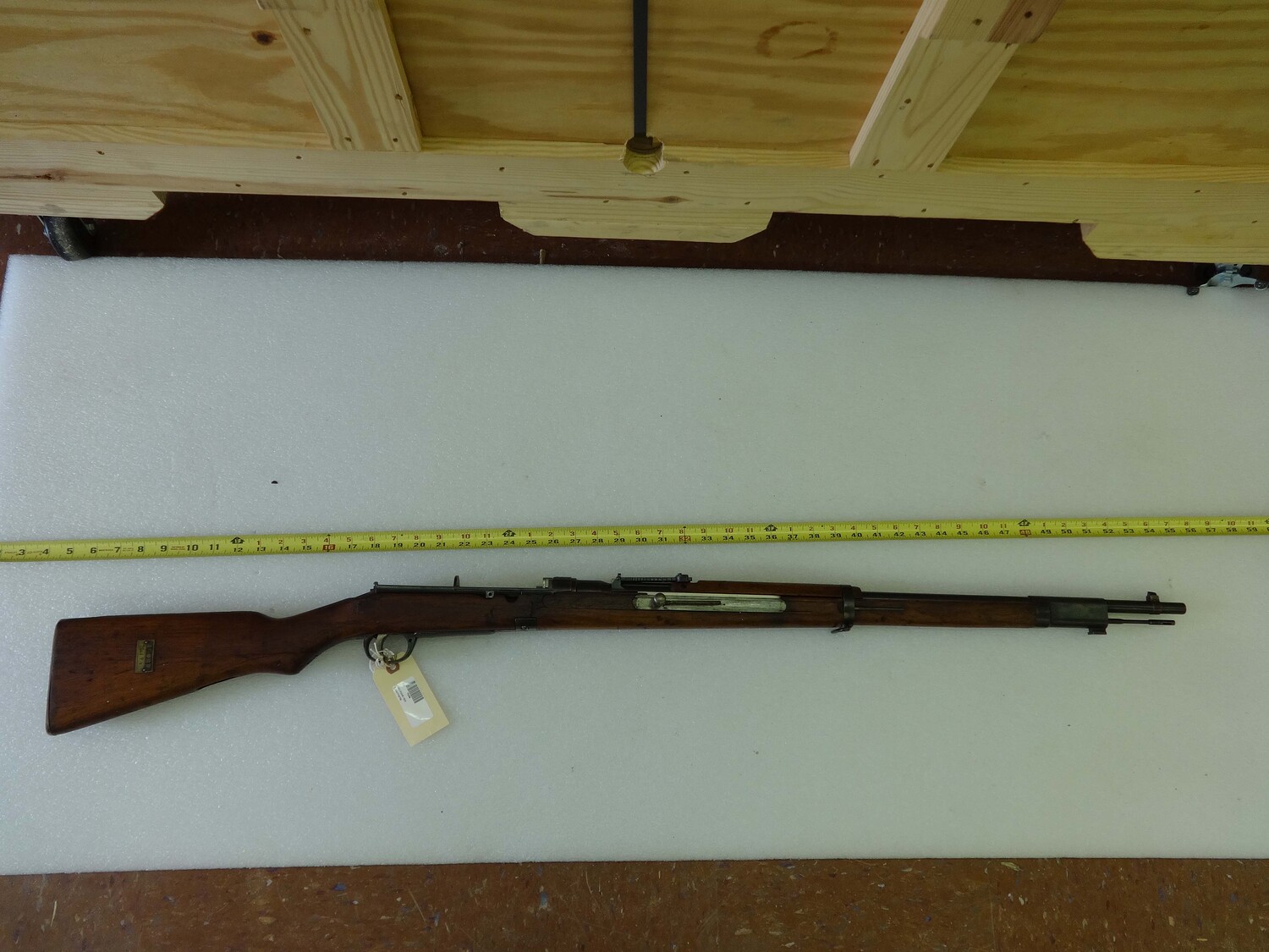
Main Specifications
-
Caliber: 6.5×50mm SR Arisaka.
-
Operating principle: Gas-operated, long-stroke forward-moving gas piston.
-
Locking mechanism: Vertically sliding locking block (
閂子) at the rear of the bolt. -
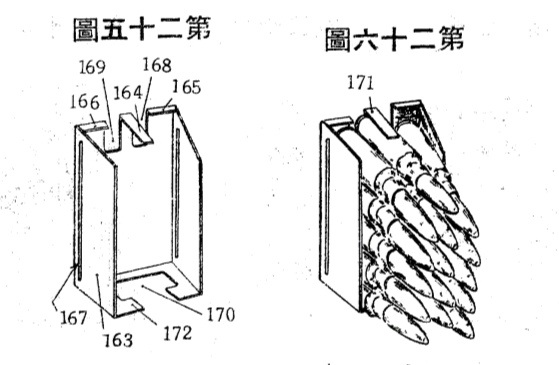
Feed system: Internal hopper-style magazine compartment at the rear of the receiver, loaded from the top with an 8-round en-bloc clip/charger (
裝塡匡) arranged in three staggered vertical columns (3–2–3 layout). Maximum capacity with a round in the chamber is 9 rounds (8+1).
Watanabe’s design aimed to accommodate a high-capacity magazine without enlarging the external profile of the stock around the receiver and bolt (preserving the grip ergonomics and balance of the standard Type 38 infantry rifle).

The interior of the receiver (2 ) is divided by a central transverse partition (79 ) into front and rear chambers. The front half forms the operating space for the bolt (3 ) and hammer (14 ), while the rear half (located behind the locking mechanism, above the trigger guard) forms the magazine compartment (55 ).
The bolt (3 ) is L-shaped; its vertical rear section closes the breech end of the chamber via the bolt head (4 ), while its long frame-like horizontal section extends far forward into the fore-end beneath the barrel, reaching approximately the midpoint of the rifle.
Because the magazine is situated behind the bolt, feeding occurs in two stages via a longitudinally reciprocating feed slide (16 ). During its forward stroke, the feed slide strips the bottom cartridge from the rear magazine compartment (55 ) and pushes it forward underneath the central partition (79 ) onto an intermediate feed tray (corresponding to the standard magazine position of a Type 38 rifle). Once the base of the cartridge clears the front edge (73 ) of the magazine wall (55 ), this shoulder retains the cartridge and prevents it from moving backward when the feed slide retracts, allowing the bolt to chamber the round on its subsequent forward stroke.
Upon firing, propellant gases drive the gas piston (22 ) and piston rod (19 ) forward , pulling the feed slide (16 ) along with them. During this forward travel, three springs are compressed simultaneously: the return (counter-recoil) spring (18 ), the recoil (bolt-opening) spring (17 ), and the hammer spring (15 ). Near the end of its forward stroke, a raised cam ridge on the feed slide pushes the straddling legs of the locking block (12 ) upward, unlocking the bolt. As the feed slide begins its rearward return stroke, the locking block (12 ) catches on a notch (75 ) on the feed slide, temporarily locking the return spring (18 ) in its compressed state; consequently, the bolt, hammer, and feed slide are driven rearward as a single unit solely by the expanding recoil spring (17 ). At the end of the rearward stroke, lateral projections (71 ) on the locking block ride up over cam projections (76 ) inside the receiver, disengaging the locking block legs from the notch (75 ) and releasing the return spring (18 ), which immediately propels the bolt forward to chamber the waiting cartridge and drop the locking block back into battery.
The extractor (10 ) is a rigid, non-spring-loaded claw protruding from the top of the bolt head (4 ), working in tandem with a U-shaped resilient wire whose tips (11 ) protrude below the bolt face to support the lower rim of the cartridge case and hold it aligned with the bore axis during extraction. At the end of the rearward stroke, the rear end of the ejector rod (8 ) strikes the central partition (79 ) of the receiver, kicking the lower rim of the spent case и ejecting it upward through the ejection port (61 ).

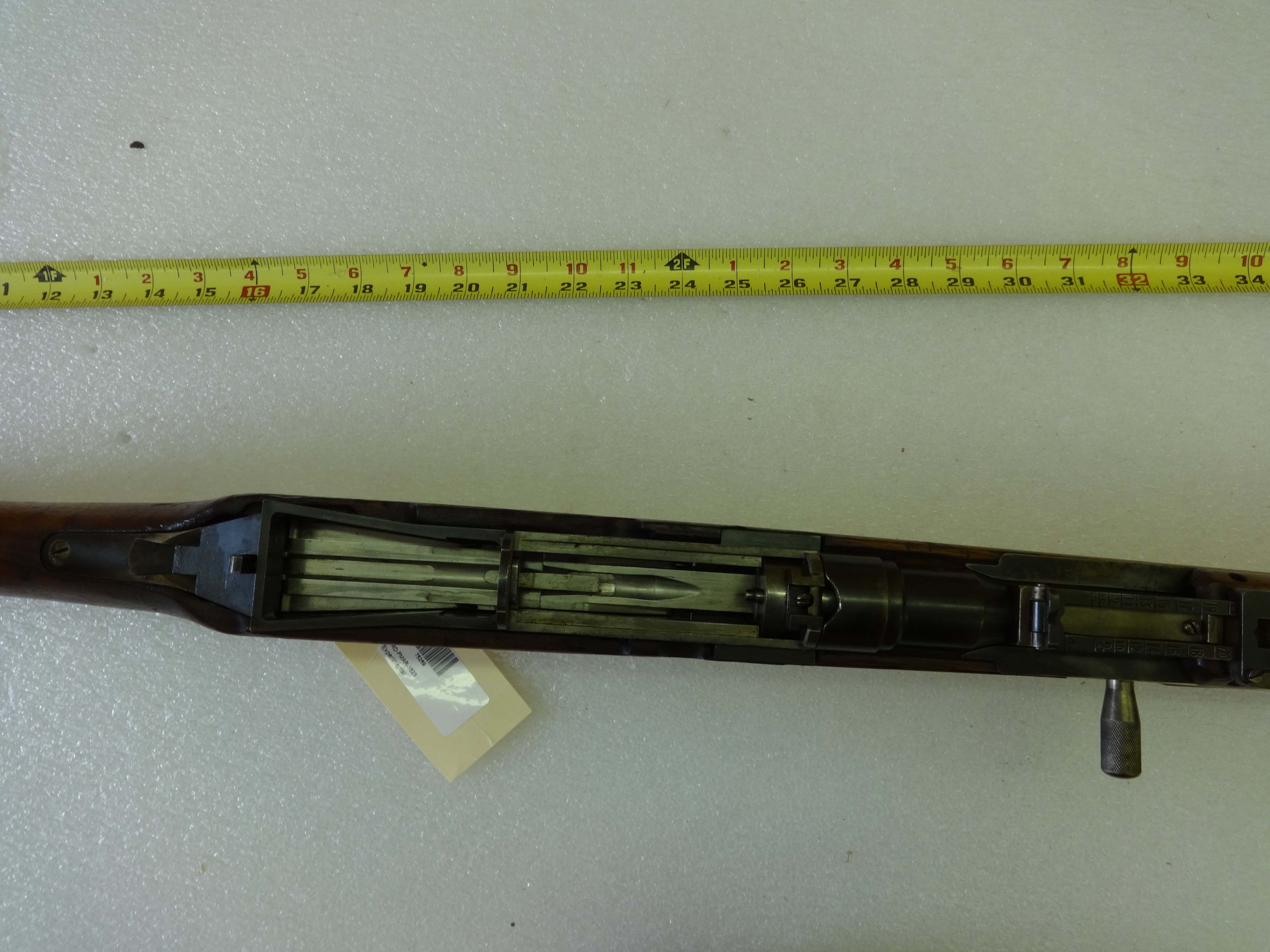
On the surviving museum specimen, the upper stamped sheet-metal covers are missing, leaving the internal receiver rails completely exposed from above. Based on the patent text and the machined seating cuts on the physical receiver, the upper cover assembly is reconstructed as follows:
-
Fixed Front Receiver Cover (
60): Covered the front chamber of the receiver between the central partition (79) and the barrel breech (between the 21-inch and 26-inch marks). This cover housed the ejection port (61), which was sealed from underneath by a sliding dust cover (62) that opened the port only when the bolt reached its rearmost position. During magazine loading, the front cover (60) remained stationary. -
Hinged Magazine Cover (
56) with Forward-Offset Pivot Pin (80): Covered the rear magazine compartment (between the 16.5-inch and 21-inch marks) and was secured at the rear by a spring-loaded latch (58). Mounted inside the dome of the cover was a long looped flat spring (53) with a follower shoe (54) that pressed downward on the cartridge column. To prevent the cover and its bulky internal spring (53) from overhanging the front of the magazine well when opened—which would obstruct vertical insertion of the 8-round clip—the pivot pin (80) was offset forward ahead of the partition (79) to the 23–23.5-inch mark. Extending forward from the dome of the magazine cover (56) along the outer side walls of the front compartment (riding inside shallow milled recesses clearly visible on the museum specimen) were two flat side arms pinned to the transverse pivot axis (80) on the outside of the receiver (尾筒ノ外側ヨリ軸止セラレ). When the rear latch (58) was depressed, the cover pivoted clockwise by 90° around the forward pin (80) like a helmet visor, swinging upward and forward in an arc to stand vertically above the fixed front cover (60), completely clearing the magazine opening (55).
Behavior of Moving Parts During Firing:
-
Forward-and-back reciprocation of the charging handle: The cylindrical knurled charging handle (
27) is located on the right side of the fore-end beneath the rear sight leaf and is screwed directly into the front end of the feed slide (16), while its slot is covered by a long sliding metal dust cover (29). With every shot fired, the charging handle (27) and its slot cover (29) reciprocate sharply forward (toward the muzzle) and then return rearward to their starting position. -
Piston rod protrusion beneath the muzzle: With every shot, the front tip of the gas piston rod (
19) briefly protrudes forward out of the gas cylinder cap (23) beneath the front sight block and retracts. -
Ejection port dust cover operation: The top ejection port (
61) on the front cover (60) is normally closed from below by the sliding cover (62). During firing, after the charging handle on the fore-end reaches its forward limit and travels back, the sliding cover (62) briefly retracts with the bolt to expose the port, ejecting the spent casing upward and to the right before immediately snapping shut.
Full Reload Animation (Empty Weapon):
-
The soldier presses the rear latch (
58) behind the magazine with their thumb and flips the magazine cover (56) forward and upward by 90° (the cover swings on its external side arms to stand vertically above the midsection of the receiver). -
An 8-round clip is inserted vertically from above into the open magazine compartment (
55) (there is no automatic clip ejection like on the M1 Garand—the clip does not fly out upon firing the last round). -
The soldier pulls the magazine cover (
56) down and back until it clicks into the rear latch (58), compressing the internal flat spring (53) against the cartridges. -
Chambering the first round: The soldier reaches forward with their right hand to grasp the knurled charging handle (
27) on the fore-end, pushes the handle forward all the way toward the muzzle, and releases it. Pushing the handle forward advances the feed slide to move a cartridge from the rear hopper onto the intermediate feed tray while compressing the operating springs; upon release, the handle returns rearward and the bolt automatically cycles to chamber the round.
Because the rear magazine compartment (55 ) is separated from the chamber and bolt by the central partition (79 ), during a tactical reload or top-off (including loading a 9th round for an 8+1 capacity), the soldier simply opens the magazine cover (56 ), tops up the compartment from above, and closes the cover (56 ) without needing to push the charging handle (27 ) forward.
Japanese Patent No. 104319
Patent Translation
Patent No. 104319 〔Publication No. 4066 of Shōwa 8 (1933)〕 Class 39, Section 10. Machine Guns
SPECIFICATION Improvement in Automatic Rifles (自働銃ノ改良)
-
Application Filed: June 3, Shōwa 7 (1932)
-
Published: September 20, Shōwa 8 (1933)
-
Patented: December 23, Shōwa 8 (1933)
-
Patentee (Inventor): Saburō Watanabe (387 Kita-Shinagawa 6-chōme, Shinagawa Ward, Tokyo City)
-
(Issued January 26, Shōwa 9 / 1934)
Nature and Purpose of the Invention
The present invention relates to an automatic rifle characterized by having a feed slide (搬筒子) driven forward by the force of propellant gases so as to sequentially feed live cartridges one by one from a magazine located to the rear of the conventional magazine position (such as that seen in the Type 38 infantry rifle) into the position of said conventional magazine, whereafter the cartridge is chambered by the subsequent closing movement of the bolt. The object of the invention is to provide an automatic rifle capable of automatically loading from a magazine accommodating a large number of cartridges without enlarging the external profile of the stock in the vicinity of the bolt.
Brief Description of the Drawings
-
Fig. 1 — Longitudinal cross-sectional view of the breech mechanism.
-
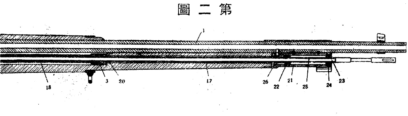
Fig. 2 — Longitudinal cross-sectional view of the front half of the rifle.
-
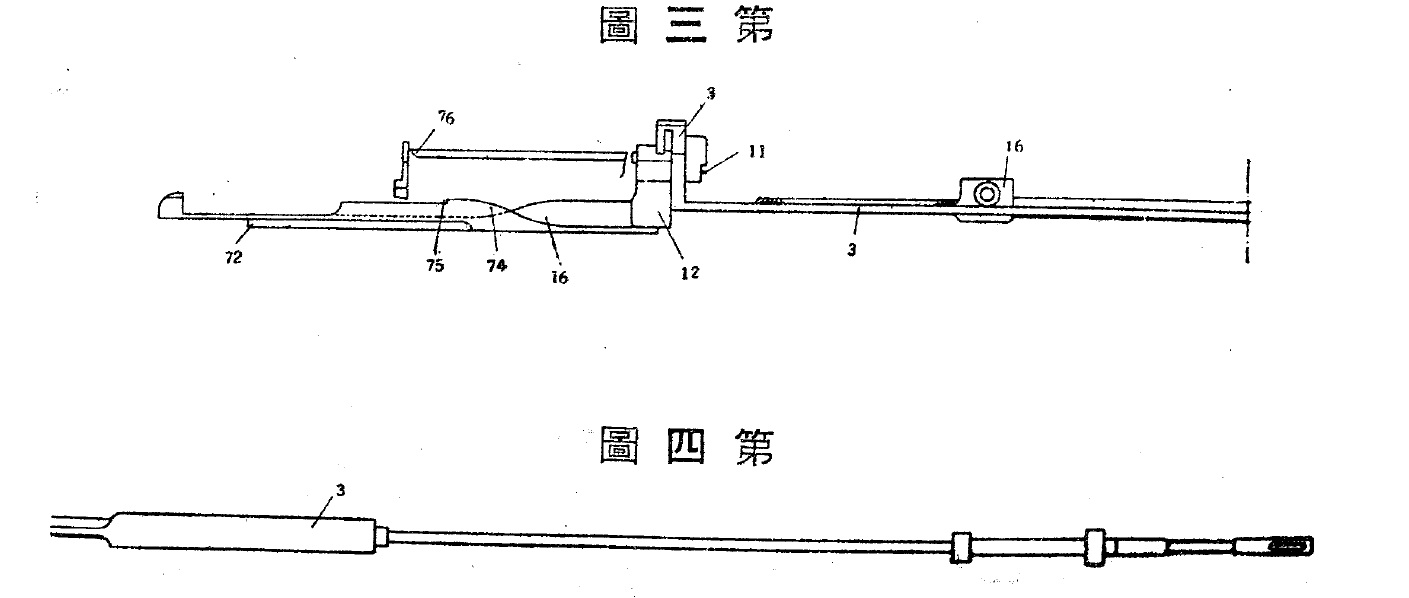
Fig. 3 — Elevation view showing the relationship between the feed slide, locking block, and bolt.
-
Fig. 4 — Elevation view showing the gas piston, piston rod, and the front half of the bolt.
-
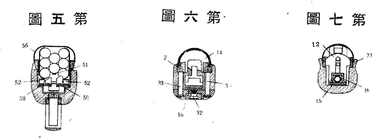
Fig. 5 — Transverse cross-sectional view of the magazine.
-
Fig. 6 — Cross-sectional view showing the relationship between the hammer, feed slide, and front support bracket.
-
Fig. 7 — Cross-sectional view showing the relationship between the locking block, feed slide, and hammer.
-
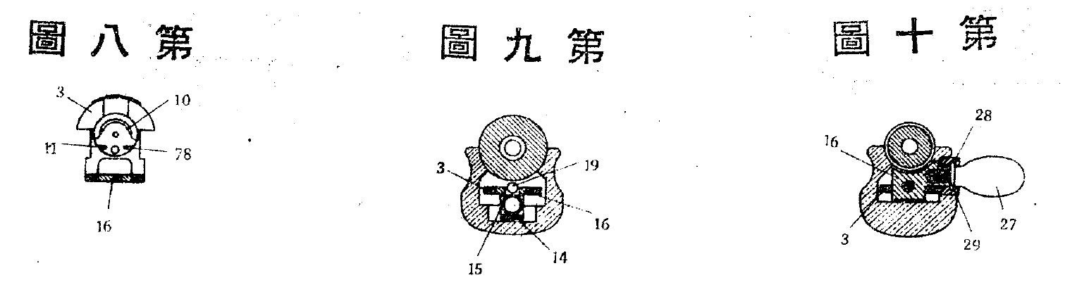
Fig. 8 — Cross-sectional view showing the relationship between the bolt head and bolt.
-
Fig. 9 — Cross-sectional view at the chamber.
-
Fig. 10 — Cross-sectional view of the front end of the feed slide.
-
Fig. 11 — Cross-sectional view of the front end of the bolt.
-
Fig. 12 — Cross-sectional view of the recoil spring housing.
-
Fig. 13 — Front elevation view of the gas chamber.
Detailed Description of the Invention
For convenience of explanation, the description is divided into the following sections: (I) Structure: (a) Receiver; (b) Bolt; (c) Feed Slide; (d) Hammer; (e) Trigger; (f) Piston Rod and Gas Piston. (II) Operation: (a) Firing Mechanism; (b) Forward Stroke of the Feed Slide and Feeding Mechanism; (c) Rearward Stroke of the Feed Slide and Bolt Opening; (d) Bolt Locking; (e) Extraction and Ejection Mechanism; (f) Manual Bolt Operating Mechanism; (g) Magazine; (h) Receiver Fastening Arrangement.
(I) Structure
(a) Receiver (尾筒) As shown in Fig. 1, the receiver (2) has a partition (79) in its center dividing it into front and rear chambers; the front half forms the space in which the bolt (3) and hammer (14) reciprocate, while the rear half serves as a magazine and accommodates a group of cartridges as shown in Fig. 5.
(b) Bolt (遊底) The bolt (3) is L-shaped; its long horizontal portion extends beneath the barrel (1), reaching approximately the middle of the rifle as shown in Figs. 1 and 2, while its vertical rear portion closes the rear end of the chamber via the bolt head (4). At the rearmost part of the bolt is a vertical groove into which a vertically slidable locking block (12) is fitted, as shown in Figs. 3 and 7. Furthermore, the horizontal portion of the bolt is frame-shaped, enclosing in its center the front end of the feed slide (16), the left [rear in the drawing] half of the piston rod (19), the return spring (18), and related parts; the foremost end of the bolt, as shown in Fig. 11, has an aperture through which the recoil spring compression tube (20) and piston rod (19) pass, with the return spring disposed around the outer circumference of said recoil spring compression tube (20), supporting its front end. Additionally, the bolt head has a central bore accommodating the firing pin (6) and firing pin spring (7), which is driven forward by the hammer (14).
(c) Feed Slide (搬筒子) The rear end of the feed slide (16) passes beneath the bottom of the magazine, while its front end lies beneath the rear underside of the barrel where the piston rod (19) is screwed into it as shown in Fig. 1. Its central portion is hollowed out from underneath to accommodate the hammer spring (15). The cross-section of the central portion is saddle-shaped as shown in Fig. 7, and is straddled by the locking block (12).
(d) Hammer (擊鐵) The hammer (14) has a 山 -shaped (channel-shaped) cross-section; as shown in Fig. 6, its central section embraces the feed slide (16) from the outside, while its front end bends upward as shown in Fig. 1 to support the hammer spring (15), constantly urging the hammer to slide forward. Its rear end is slotted in the center to hold the hammer sear (44) on a pivot pin (46); said sear (44) is constantly urged to rotate counterclockwise by the hammer sear spring (45).
(e) Trigger (引鐵) The trigger (38), as shown in Fig. 1, is pivoted in a hole (43) in the trigger guard (30), and at a hole (42) at its front end pivots a bifurcated trigger bar (39) that straddles it from above. It also has an inclined bore accommodating a trigger plunger (40) and trigger plunger spring (41), which impart a clockwise rotational bias to said trigger bar.
(f) Piston Rod and Gas Piston (朔杖及活塞) As shown in Fig. 2, after pre-assembling the piston support tube (25), gas chamber cap (23), and gas piston (22), the piston rod is inserted from the front of the rifle, passing through the erosion shield bushing (26), recoil spring (17), and recoil spring compression tube (20), and screws into the female thread at the front end of the feed slide (16) as shown in Fig. 1.
(II) Operation
(a) Firing Mechanism (發火裝置) When the trigger (38) is pulled, it rotates clockwise around the pin (43), causing the front end of the trigger bar (39) to pull down the lower end of the hammer sear (44); the nose of the hammer sear (44) disengages from the cam ridge (72) 〔Fig. 3〕 of the feed slide, allowing the hammer to be driven forward by the hammer spring (15) and strike the rear end of the firing pin (6) at the end of its travel, whereby the firing pin compresses the firing pin spring (7) and strikes the primer to fire the cartridge. At this time, the locking block (12) is in its lowest position, engaged in the vertical recess of the receiver, firmly locking the breech. Should the locking block fail to reach its lowest position, the rear end of the locking block (12) blocks the hammer from striking the firing pin, thereby preventing premature firing.
(b) Forward Stroke of the Feed Slide and Feeding Mechanism (搬筒子ノ前走及給彈裝置) 〔See Figs. 2 and 1〕 Propellant gases pass through the gas port into the gas chamber (21) and push the piston (22) forward, causing the piston rod 〔Figs. 9, 10, 11〕 and feed slide (16) to move forward and compress the return spring (18). Simultaneously, the recoil spring compression tube (20) also moves to the right [forward in the drawing] , compressing the recoil spring (17). At the same time, the hammer spring—which had expanded upon firing as described above—is re-compressed from the rear by the forward movement of the feed slide (16). During this forward stroke, the feed slide carries one cartridge out of the magazine; once the rear end of said cartridge passes ahead of the front edge (73) of the magazine wall (55), that shoulder supports the cartridge alone during the subsequent rearward stroke of the feed slide and prevents the cartridge from moving back. Furthermore, during the forward stroke of the feed slide, the two legs of the straddling locking block (12) 〔Figs. 3, 7〕 are pushed upward by the raised cam ridge near the middle of the feed slide, unlocking the bolt. Continuing slightly further (overtravel) to fully compress the three aforementioned springs, the feed slide stops and immediately reverses into its rearward stroke.
(c) Rearward Stroke of the Feed Slide and Bolt Opening (搬筒子ノ後退ト遊底開放) 〔See Fig. 3〕 Having completed its forward stroke, the feed slide immediately begins its rearward movement; midway through, the locking block sliding over the cam ridge (74) catches on the corner notch (75) of the ridge, thereby locking the return spring, while simultaneously the hammer sear (44) catches on the tooth of the lower ridge (72) on the underside of the feed slide, locking the hammer spring. Consequently, from this point onward, the bolt, hammer, and feed slide move rearward together as a single unit driven solely by the recoil spring (17). During this rearward movement, the rear end of the feed slide slightly lifts the cartridges inside the magazine as it retracts and comes to rest in the position shown in Fig. 1. Simultaneously, the left and right lateral projections (71) 〔Fig. 7〕 of the locking block (12) ride up onto the projections (76) 〔Fig. 3〕 of the receiver, disengaging both legs of the locking block from the corner notch (75) of the feed slide, releasing the lock on the return spring so that the bolt begins to move forward again.
(d) Bolt Locking (遊底閉鎖) 〔See Fig. 1〕 As soon as the return spring is released, the bolt immediately commences its forward stroke, simultaneously pushing the base of the previously fed cartridge into the chamber. Upon completion of bolt closure, because the locking block (12) is constantly urged downward by the locking block spring (13), it drops into the position shown in Fig. 1 to lock the rear end of the bolt, firmly maintaining the bolt in its locked state until the feed slide pushes the locking block upward again.
(e) Extraction and Ejection Mechanism (抽筒裝置及蹴出裝置) The extractor (10) does not have a spring-loaded resilient claw as seen in conventional firearms, but is a rigid claw-shaped projection protruding from the bolt head that engages the upper half of the cartridge case rim as shown in Fig. 8. At the bottom of the bolt head (4) is a groove (78) 〔Fig. 8〕 clamping a U-shaped resilient wire between the bolt head and the bolt, whose tips (11) protrude approximately 2 mm ahead of the bolt face as seen in Figs. 3 and 8. When a cartridge is pushed by the bolt head into the chamber, this resilient wire is spread apart by the diameter of the case rim, and once the cartridge case aligns with the bore axis, the wire springs inward beneath the cartridge to support the case from below; during bolt retraction, the upper edge of the rim is held by the extractor while the lower edge is supported by said resilient wire, keeping the case aligned with the bore axis as it travels rearward until, near the end of the rearward stroke, the rear end of the ejector (8) 〔Fig. 1〕 strikes the central partition (79) of the receiver, compressing the ejector spring (9) so that the front end of the ejector kicks the lower rim of the empty case and ejects it through the ejection port (61). The ejection port is covered from below by an ejection port cover (62) that opens the port only when the bolt is in its rearward position.
(f) Manual Bolt Operating Mechanism (遊底ノ手動裝置) Screwed into the right side of the front end of the feed slide, as seen in Fig. 10, is an operating handle (27); pushing it forward by hand advances the feed slide and actuates the mechanism in the exact same manner as when gas pressure drives the piston forward, serving both to chamber the very first round and to unload a live cartridge without firing. The operating handle rides within a handle slot (28) covered by a slot cover (29); when the feed slide reciprocates, the handle and slot cover move forward and backward together with it.
(g) Magazine (彈倉) The magazine cover (56) is pivotally mounted at its front end on a pin (80) from the outside of the receiver as shown in Fig. 1, and rotates clockwise around it to stand vertically and open the magazine. Cartridges are held together in a loading clip (裝塡匡 ) and loaded as shown in Fig. 5.
(h) Receiver Fastening Arrangement (尾筒緊定裝置) Because the reciprocating feed slide passes through the center of the rifle, the receiver is not fastened to the stock in the conventional manner; instead, two front receiver retaining screws (33) and a front support bracket (31) are provided to secure the assembly as shown in Fig. 6. The feed slide and hammer slide back and forth in the space between these two front receiver retaining screws.
Scope of Claims
An automatic rifle characterized by having, as described in detail in the text and clearly shown in the accompanying drawings, a feed slide (搬筒子 ) driven forward by the force of propellant gases so as to sequentially feed live cartridges one by one from a magazine located to the rear of the conventional magazine position (such as that seen in the Type 38 infantry rifle) into the position of said conventional magazine, whereafter the cartridges are chambered by the subsequent closing movement of the bolt.
Supplementary Claims (附記):
-
An automatic rifle according to the Scope of Claims, wherein, as described in detail in the text and clearly shown in the accompanying drawings, the forward stroke of the feed slide is effected by gas pressure acting upon a gas piston connected thereto.
-
An automatic rifle according to the Scope of Claims, wherein, as described in detail in the text and clearly shown in the accompanying drawings, the disengagement (unlocking) of the locking block takes place during the final stage of the forward stroke of the feed slide.
-
An automatic rifle according to the Scope of Claims combining two types of springs, wherein, as described in detail in the text and clearly shown in the accompanying drawings, the reciprocating movement of the bolt is effected by a recoil spring and a return spring that are both compressed during the forward stroke of the feed slide.
-
An automatic rifle according to the Scope of Claims, wherein, as described in detail in the text and clearly shown in the accompanying drawings, the front end of the hammer spring is supported by a portion of the hammer and the rear end is supported by a portion of the feed slide.
-
An automatic rifle according to the Scope of Claims, wherein, as described in detail in the text and clearly shown in the accompanying drawings, the receiver and the magazine floorplate are secured together by means of a front support bracket (31), a magazine floorplate front retaining screw (32), and two receiver front retaining screws (33).
-
An automatic rifle according to Supplementary Claim 1 of the Scope of Claims, wherein, as described in detail in the text and clearly shown in the accompanying drawings, the connection between the gas piston and the feed slide is effected by a detachable piston rod.
-
An automatic rifle according to the Scope of Claims, wherein, as described in detail in the text and clearly shown in the accompanying drawings, the extractor (10) is rigidly mounted relative to the bolt.
-
An automatic rifle according to the Scope of Claims, wherein, as described in detail in the text and clearly shown in the accompanying drawings, the bolt is L-shaped, with its horizontal portion extending beneath the barrel and only its vertical portion positioned behind the chamber to close the breech.
-
An automatic rifle according to the Scope of Claims, wherein, as described in detail in the text and clearly shown in the accompanying drawings, the hammer or bolt is provided with a clearance opening in the central part of the rifle approximately 1 cm below the bore axis to allow a cartridge fed from the rear to pass through.
-
An automatic rifle according to the Scope of Claims, provided with an ejection mechanism having the construction, arrangement, and operation as described in detail in the text and clearly shown in the accompanying drawings.
-
An automatic rifle according to the Scope of Claims, provided with a manual bolt operating mechanism having the construction, arrangement, and operation as described in detail in the text and clearly shown in the accompanying drawings.
-
An automatic rifle according to the Scope of Claims, provided with a magazine having the construction, arrangement, and operation as described in detail in the text and clearly shown in the accompanying drawings.
-
An automatic rifle according to the Scope of Claims, provided with a trigger mechanism having the construction, arrangement, and operation as described in detail in the text and clearly shown in the accompanying drawings.
Polls
- Yes
- No
- Event — individual weapon
- Event — squad weapon
- Tech Tree (Research Tree)
- Premium squad
- Battle Pass
- BR II
- BR III
- BR IV
