The project of the experimental self-loading rifle No3 designed by Saburo Watanabe is the least known of the entire line of developments of the Nippon Special Steel Company. This experimental design of 1932 includes some elements of early developments, as well as a number of alternative and original technical solutions
On June 3, 1932, the Japanese Patent Office received application No 4066, entitled “Improved Automatic Rifle”.
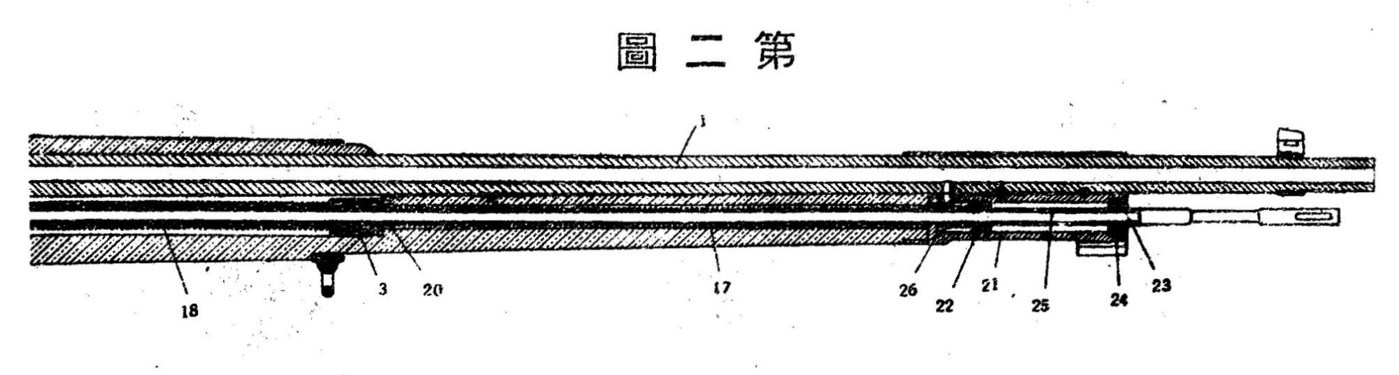
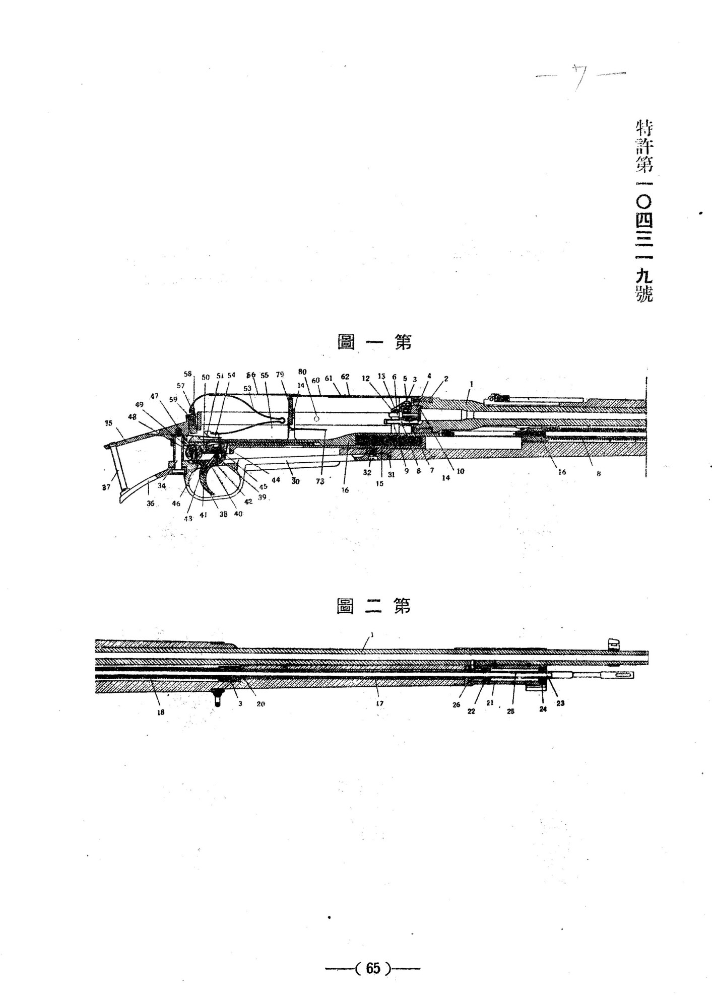
The purpose of the development of this project by Saburo Watanabe was to obtain a self-loading rifle with a gas-operated automatic system (with a long piston stroke), with a simplified bolt locking scheme, a multi-shot magazine with a batch version of loading cartridges. The inner cavity of the bolt box is divided into two halves - the front one for the bolt with a firing pin and ejector, and the rear one for the bundle magazine with a spring.
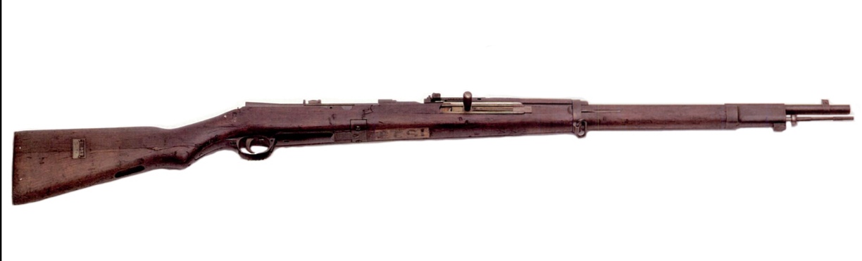
In general, the Project No3 semi-automatic rifle was supposed to be simple enough for mass production and available for mastery by military personnel already familiar with the standard 6.5mm Arisaki Type 38 infantry rifle.
A feature of the self-loading rifle project was the location of the magazine (on top in the breech, behind the bolt), and the associated method of interaction between the reloading mechanisms and the automatic cycle.

To load the rifle, the shooter took hold of the magazine cover body (56) and, pulling it back, opened access to the loading window (55).
At the same time, the flat plate spring of the magazine (53) with a feeder (54) installed at its lower end was compressed, sliding backwards along the inclined guides of the bolt box.
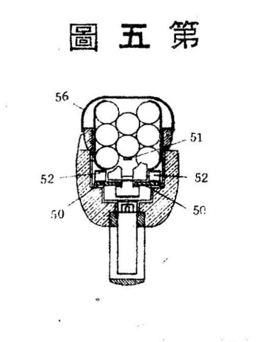
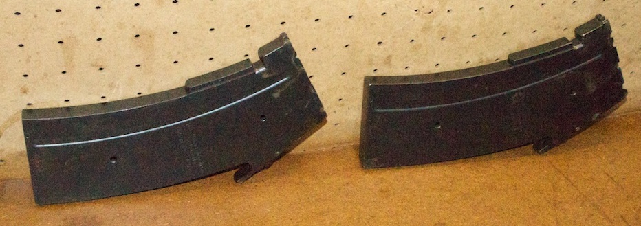
An eight-shot clip (51) with a three-row arrangement of 6.5x50SR cartridges is installed in the loading window (55).
The magazine cover (56) moves forward, closing the loading window. The leaf spring (53) with the feeder (54) is compressed in the upper position by the cartridges in the pack.
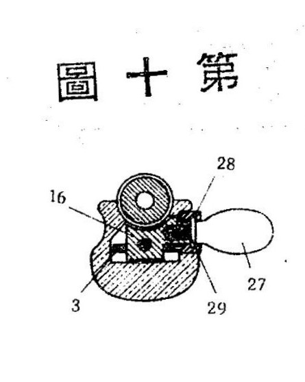
On the right side there is a loading handle (27) of the bolt carrier (16) on a spring-loaded axis. When the loading handle is pressed, it aligns with the hole in the bolt carrier (16).
The rifle is loaded with the first two cartridges in two steps.
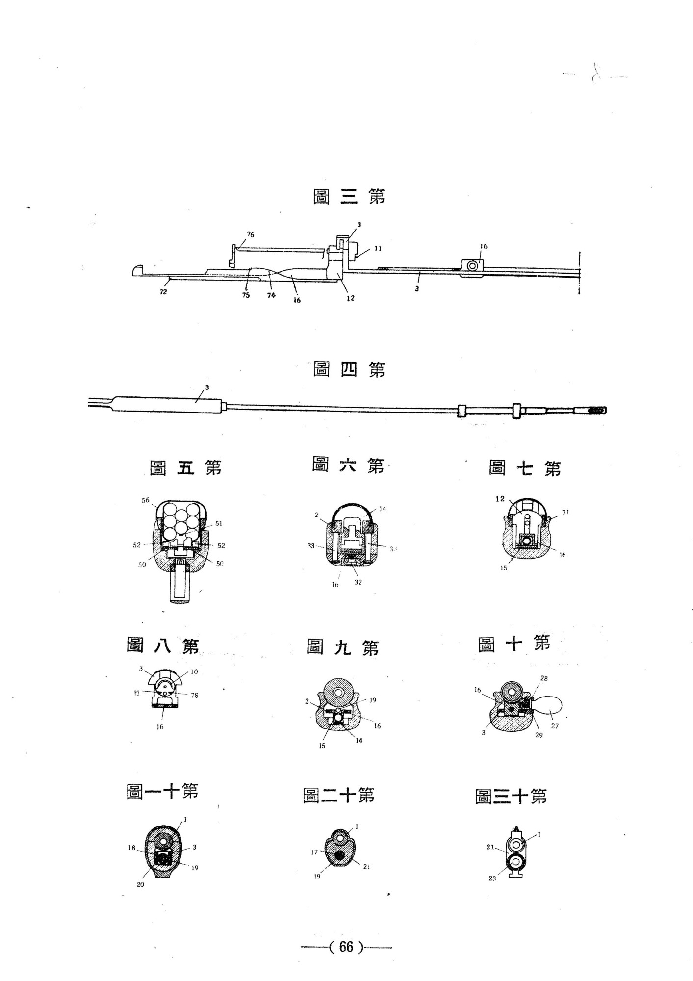
The first forward movement behind the loading handle (27) is to remove the first lower (right) cartridge from the bundle with a bolt carrier hook, which hits the rammer rack (74-75).
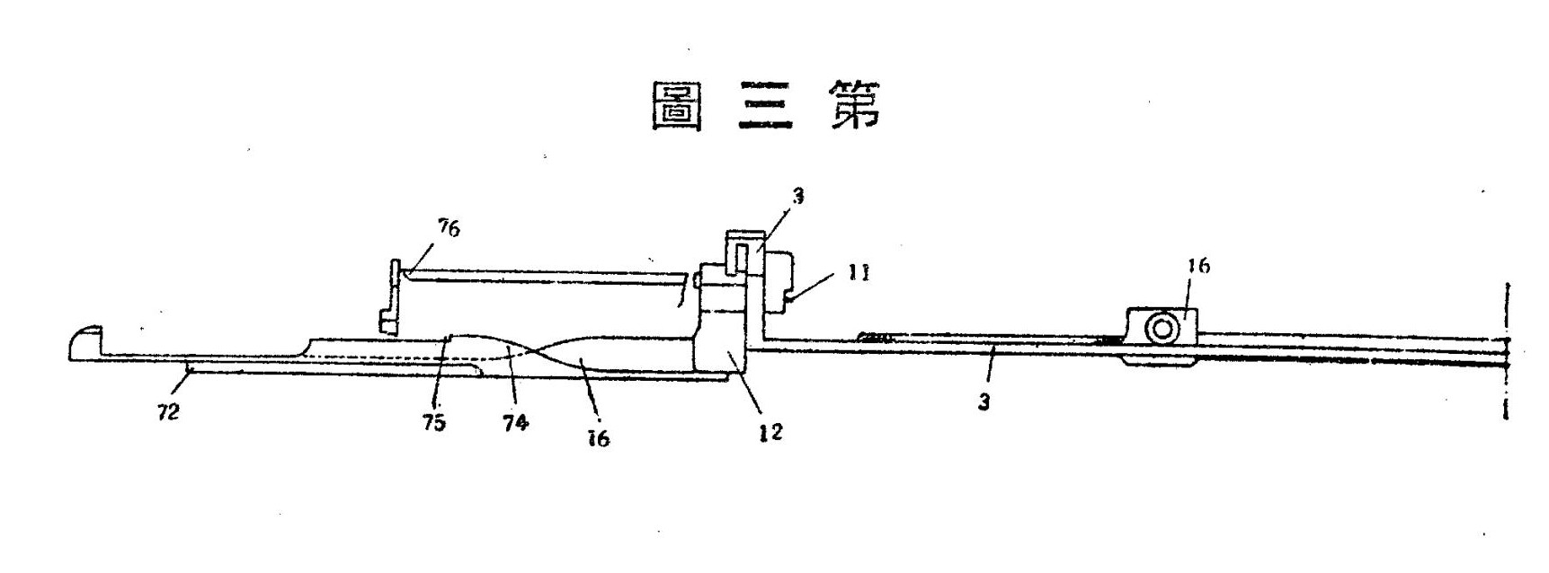
The bolt carrier compresses two springs - the return (18) of the gas exhaust rod and the disconnector (7), the rammer rack (74-75) with the bolt carrier (16) with the gas exhaust rod screwed into it (17).
The loading handle brought to the extreme forward position is released, returning to the original rear position.
With the second forward movement of the bolt loading handle (27), the first cartridge from the rammer rail (74-75) is directed to the chamber along inclined guides. At this moment, the bolt carrier hook (16) hooks the second lower cartridge from the pack and moves it to the rammer rack (74-75).
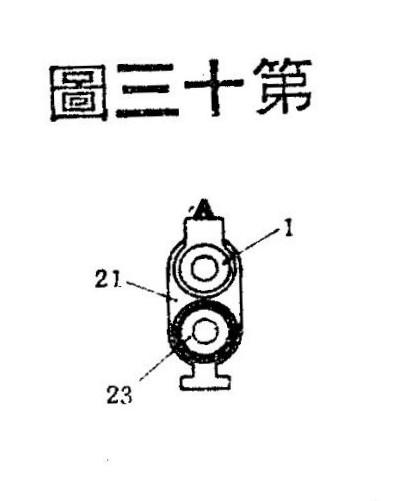
When firing, part of the powder gases enters through the side hole in the barrel bore into the underbarrel gas exhaust mechanism (the volume of gas extraction is constant, there is no adjustment).
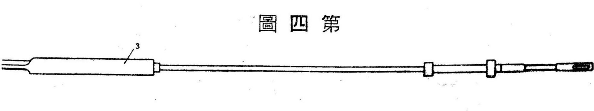
The gas piston rod (23) is pushed forward by powder gases. The bolt carrier (16) connected to the rod also moves forward, compressing the common spring of the disconnector (7) and the rammer racks (74-75).
The rammer rack (74-75) due to its spiral (45 degrees counterclockwise) guide bevels directs the second chuck to the ramming line.
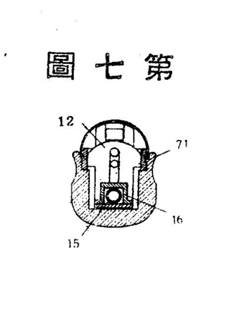
The upper bevel on the bolt carrier (16), interacting with the locking wedge (12), pushes it up the vertical grooves (71) in the bolt box, locking the bolt (11).
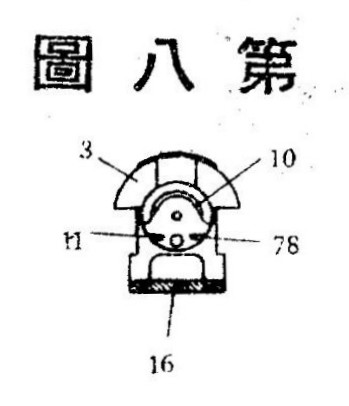
The bolt (11) after firing under the influence of powder gases (pressing on the bottom of the cartridge case) rolls back, removing the spent case by the rim with a wide hook of the extractor (10). The ejection of the case up and to the right occurs after the impact of the bottom of the case on the front end of the reflector (76), which also serves as the guiding axis of the bolt (11).
Together with the bolt (11), the rammer rack (74-75) moves back to the extreme position, compressing the disconnector spring (7). The gas piston rod (23) with the bolt carrier (16) returns to the rear position under the action of its own spring (18).
The rammer rack hook (74-75) hooks the third cartridge from the clip from below.
Under the action of the disconnector spring (7), the lower part of the rammer rack (8) moves forward together with the bolt (11).
The bolt hooks the lower edge of the second cartridge from the ramming line and directs it into the chamber. The bolt is closed and locked by a rising wedge (12) sliding with the lower surface along the inclined bevel of the rammer rack (16).
The rifle is ready for the second shot.
In a simplified description, the procedure consists of four phases:
Phase I. Bolt handle forward. The gas exhaust rod moves forward. Compression of two springs. Bolt unlock, Cartridge No1 on the ramming rail.
Phase II. The bolt handle is backwards. The gas exhaust rod is pushed back. Straightening the gas rod spring. The bolt moves back. Engagement of the No1 cartridge with the bolt. Cartridge No2 on the ramming rail.
Phase III. The bolt moves forward by the spring of the disconnector. No1 cartridge in the chamber.
Phase IV. Shot. The gas rod moves forward. Compression of two springs. Unlocking the shutter.
Afterword.
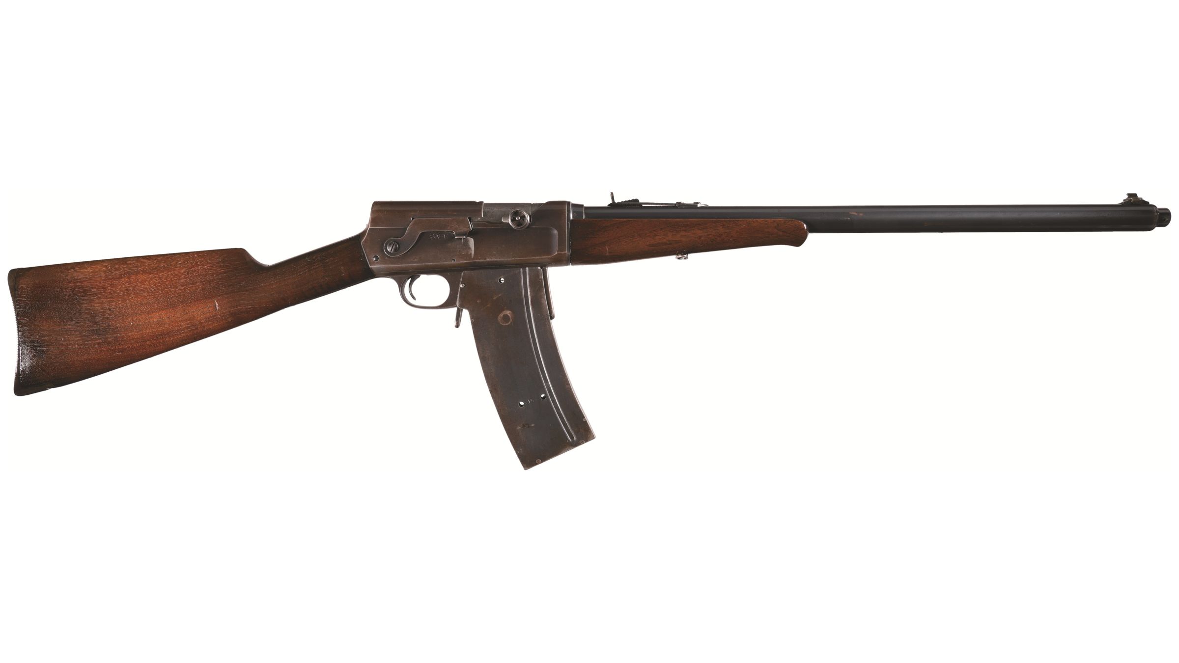
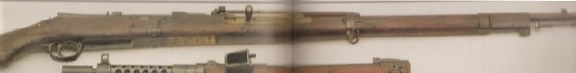
The third project of an experimental semi-automatic rifle, Saburo Watanabe, received Japanese Patent No 104319 on December 23, 1933. There is no evidence of the production of an experimental batch of this rifle or testing by the Japanese army. Except for one photo from an American private collection.
Design time: 1933
Faction: Japan
Developer: Saburo Watanbe
Bullet: 6.5x50 SR
Firing mode: semi-Automatic
Bullet capacity: 8 rounds
Game weight: BR3
Acquisition method: Technology tree
Японские самозарядные винтовки Сабуро Ватанбе. ч3.: lautlesen — LiveJournal
Do you think this weapon should be included in our battlefield?.
- Yes
- No