

Work on the creation of automatic weapons in the Russian Empire began at the end of the 19th century almost simultaneously with the beginning of similar research in other industrialized countries of the world (USA, Great Britain, France, Germany, Austria-Hungary).
At the first stage of this work on the creation of an automatic rifle (until 1904), Russian gunsmiths developed several projects of such weapons: D. A. Rudnitsky (1886–1887), K. Glinsky (1888), Glubovsky and Privalov (1890s), and the Valitsky brothers.
They built their experimental work on the design basis of the serial 4.2-line rifle of the 1870 model (Berdan No 2). At the second stage of work (1904-1911), several Russian gunsmiths proposed projects of automatic rifles, most of which were based on the design of the 3-line Mosin rifle model 1891 (converted automatic rifles). At this time, the projects of automatic rifles were developed by the inventors: Shubin (1904), V. Tatsik (1904), Poznitsky (1905).
In subsequent years, the number of gunsmiths who took part in the development of automatic rifles was joined by inventors: V. G. Fedorov, Y. U. Roschepei, S. P. Khatuntsev1, N. G. Dmitriev-Baitsurov2, F. V. Tokarev, I. K. Antsus34, I. N. Kolesnikov, N. Shchukin, P. N. Frolov. In 1910-1911, other inventors submitted their projects of automatic rifles: I. Y. Staganovich and Sudakov, but they did not receive support5. At the same time, V. P. Konovalov, an employee of the Sestroretsk Arms Plant, presented his first project of an automatic rifle (1907), whose design activities this article is devoted to.

Weapons designers testing automatic rifles. Seated: V. P. Konovalov, V. G. Fedorov, F. V. Tokarev. 1920s. VIMAIViVS
The stage of the creation of early automatic rifles in Russia is most fully covered in the studies of V. G. Fedorov. In his fundamental works6 among the successful automatic rifles created before 1917 are the samples developed by himself, F. V. Tokarev and Y. U. Roschepei. However, the coverage of the activities of a number of the first Russian inventors of automatic rifles, including V. P. Konovalov, was out of the sphere of attention of V. G. Fedorov, he limited himself only to mentioning his name7.
In Russian weapons science, V. P. Konovalov is known, first of all, as the author of the design of a new sight for the Mosin rifle of the 1891 model for firing cartridges with a pointed bullet of the 1908 model (Konovalov arc sighting frame). But in the pre-revolutionary period, he also developed a nickel jacketed bullet with a tapered back8 («задком» в современном событиям написании), несколько вариантов прицельных приспособлений для винтовки обр. 1891 года (1909 г.9, 1917 г.10, а также каску-котелок11 (1916 г.).
В 1916 году В. П. Коновалов работал мастером при изобретателе 3-линейного авиационного пулемёта Владимире Фроме12, а в последующие годы он выполнил ряд усовершенствований и изобретений в области военной техники и вооружения: пика с деревянным древком13 (1917 г.), прибор для стрельбы ночью14 (1919 г.), крешерный прибор15 (1922 г.), ружейная маслёнка16 (1927 г.), стальной шлем (каска) (1927 г.)17. В начале 1920-х годов В. П. Коновалов участвовал в модернизации 7,62-мм винтовки Мосина обр. 1891 года, которая подвергалась полигонным испытаниям в 1925 году.

Модернизированная Коноваловым трехлинейная винтовка Мосина обр. 1891 г. (1925 г.). Общий вид. Новая ложа с пистолетной рукоятью и накладкой, закрывающей почти весь ствол. ВИМАИВиВС

Винтовка-Мосина-модернизация-Коновалова-затвор Модернизированная Коноваловым трехлинейная винтовка Мосина обр. 1891 г. (1925 г.). Колодка прицела смещена назад, прицельная планка получила винт боковых поправок. ВИМАИВиВС

Modernized by Konovalov three-line Mosin rifle model 1891 (1925). Bayonet in travel and combat position. VIMAIViVS
But the most valuable part of the creative heritage of V. P. Konovalov for domestic weapons science is the automatic rifles developed by him from 1907 to 1925.
In accordance with the identified documents, by December 22, 1907, V.P. Konovalov had developed a description and drawings of an automatic rifle with a fixed barrel and automatics with the removal of powder gases18. It has not yet been possible to identify this sample of the Konovalov rifle in museum collections, its appearance and other design features are unknown. It should be noted that this rifle model was the only one in the work of V. P. Konovalov, in which the gas-operated principle of automation was used. All subsequent models of his automatic rifles had an automatic system with a fixed barrel and a self-unlocking bolt with a delay in unlocking (a type of system with a semi-free bolt).
Documentary information about the rifle of this model has not yet been revealed, but its exact dated sample is stored in the collection of weapons of the Museum of Political History of Russia (St. Petersburg).

Konovalov’s three-line automatic rifle of 1914. Museum of Political History of Russia
The main technical features of the rifle include the principle of automation with a fixed barrel and a completely original design of parts and mechanisms.

Konovalov’s three-line automatic rifle (1914). Engraving indicating authorship, plant and date. Museum of Political History of Russia
The configuration of the automatics of this rifle could not be established due to the impossibility of disassembling it, but an analysis of the external parts shows that it has a fixed barrel and a non-rotating bolt, slowed down when fired by a mechanism, the essence of which is not clear for the above reason.

Konovalov’s three-line automatic rifle (1914). Museum of Political History of Russia. Bottom view of the trigger guard and magazine cover. Museum of Political History of Russia
Other features of the rifle are as follows: a permanent single-row magazine for 5 rounds. The safety is located in the trigger guard, the sight is stepped up to 3500 steps, the front sight is triangular, the ramrod is placed under the barrel. On the muzzle of the barrel there is a threaded section for attaching a muzzle device or bayonet.

Трехлинейная автоматическая винтовка Коновалова (1914 г.). Дульная часть. Виден резьбовой участок с лыской для фиксации для присоединения дульного устройства или штыка. Музей политической истории России
В прикладе находится цилиндрический канал для пенала принадлежности с защёлкой. Ствольная накладка и цевьё ложи имеют вентиляционные отверстия. Некоторые характеристики винтовки Коновалова 1914 года приведены в таблице.
A rifle of this type is stored in the collection of weapons of the Museum of Political History of Russia (St. Petersburg).

6.5-mm Konovalov automatic rifle of 1922-1923. Museum of Political History of Russia
The rifle is designed for the 6.5 mm Japanese rifle cartridge. Its main technical features include the principle of automation with a fixed barrel and a self-unlocking bolt with a delay in unlocking.

6.5-mm Konovalov automatic rifle (1922-1923). View from above. Museum of Political History of Russia
The release delay mechanism is made in the form of two spring-loaded levers (locking lugs) located in cutouts on the inner side surfaces of the front of the receiver21, as well as cutouts in the side walls of the bolt, which include the supporting ends of the stops.

6.5-mm Konovalov automatic rifle (1922-1923). Receiver. Museum of Political History of Russia
The angle at which the supporting surfaces of the lugs and the bolt come into contact is close to the angle of self-braking, which, when firing, ensures the stop of the bolt movement (delay in self-unlocking) until the moment when the pressure in the barrel decreases to a value at which the bolt can overcome the friction between it and the lugs, spread them apart and start moving in recoil, reloading the weapon. When the bolt is returned to the extreme forward position, the lugs under the action of their springs independently enter the cutouts in the bolt, locking the barrel bore.
Other features of the rifle are as follows: a permanent double-row magazine for 10 rounds, loaded from above from a clip inserted into the vertical grooves of the receiver.

6.5-mm Konovalov automatic rifle (1922-1923). Bottom view of the trigger guard, magazine and night firing rail. Museum of Political History of Russia
Ударно-спусковой механизм курковый, разобщение со срывом шептала. Предохранитель в спусковой скобе, прицел и мушка отсутствуют. Шомпол размещается в боковых каналах на боковых поверхностях ложи (в правом или левом). На крышке магазина установлена планка для ночной стрельбы с разметкой в сотнях метрах дальности.

6,5-мм автоматическая винтовка Коновалова (1922–1923 гг). Дульная часть. Видна петля крепления откидного штыка. Музей политической истории России
Штык несъёмный, откидной (вниз) с оригинальной конструкцией крепления в боевом положении (сам штык утрачен). Некоторые характеристики винтовки Коновалова модели 1922–1923 года приведены в таблице.
Документальных сведений о винтовке данной модели выявить пока не удалось, её точно датируемый образец хранится в собрании оружия ФГБУК «Музей политической истории России» (Санкт-Петербург).

6.5-mm Konovalov automatic rifle (1924). General view. Museum of Political History of Russia
The rifle is designed for the 6.5 mm Japanese rifle cartridge. Its main technical features include the principle of automation with a fixed barrel and original combined type automation with double-circuit locking of the barrel bore.
In general, in weapons with combined automation, the barrel bore is unlocked and the bolt is released by a special mechanism activated by some external force, and the bolt is ejected by residual pressure in the barrel bore.

6.5-mm Konovalov automatic rifle (1924). View from above. An inertial body and recesses for the fingers for cocking are visible. Museum of Political History of Russia
The described principle of automatics was used in many models of automatic weapons developed in different countries of the world, including Russia23, some of the later and fairly advanced models of automatic weapons have automatics containing features of a combined type24. However, V.P. Konovalov implemented the principle of combined automatics in the described rifle in a special way, introducing an additional mechanism for delaying the self-unlocking of the bolt, thus performing double-circuit locking.

6.5-mm Konovalov automatic rifle (1924). Museum of Political History of Russia. General view of the automation mechanism
In the primary locking circuit, the barrel bore is rigidly locked by the bolt using two side locking lugs located in the front of the receiver and included in the transverse cutouts in the bolt. The separation of the stops to the sides and the release of the bolt from the rigid connection with the box is carried out by an inertial body - the bolt carrier (a massive cylindrical sleeve worn on the breech of the barrel), which, when the rifle moves backwards under the action of recoil, remains in place relative to the receiver moving in the recoil and spreads the stops.

6.5-mm Konovalov automatic rifle (1924). Museum of Political History of Russia. Bottom view of the wolk box without stock
After that, the second locking circuit is activated, in which the bolt is held from free recoil by friction between the base of the bolt handle and the screw surface of the receiver, the angle of which is close to the angle of self-braking.
The second locking cage keeps the bolt from free recoil until the pressure in the barrel bore decreases to a value at which the bolt can overcome the friction of the handle on the screw cutout in the box, turn and start moving in recoil, reloading the weapon.

6.5-mm Konovalov automatic rifle (1924). Original sighting device. Museum of Political History of Russia
To prepare the rifle for firing during the first loading, it is necessary to first move the inertial bolt carrier forward until it is latched (two cutouts are made in its side walls for finger rests). Next, in the usual manner, pull back and release the bolt, sending a cartridge into the chamber, after which the bolt carrier, automatically removed from the latch, will go back and bring the lugs together and lock the barrel bore.
Konovalov’s double-circuit locking allows you to delay the release of the bolt until the pressure in the barrel bore is significantly reduced, but complicates the design of the rifle and its handling. The authors do not exclude that the combination of the principle of automation and locking mechanisms used in this rifle is original and one of a kind.

6.5-mm Konovalov automatic rifle (1924). Muzzle. Height-adjustable front sight with earpiece. Museum of Political History of Russia
Other features of the rifle are as follows: detachable single-row magazine for 5 rounds. The trigger mechanism is hammer, disconnection with a sear stall. The safety is located in the trigger guard. The arc sight is marked up to 2000 m, has a horizontally adjustable rear sight. The front sight is triangular, adjustable in height. The ramrod is placed in the side channels on the side surfaces of the stock (right or left). The bayonet is non-removable, folding (down) with an original design of fastening in the firing position (the bayonet itself is lost). Some characteristics of the 1924 Konovalov rifle are given in the table.
A sample of this type of rifle is stored in the collection of weapons of the Museum of Political History of Russia (St. Petersburg).

7.62-mm Konovalov automatic rifle of 1925 (first model). Museum of Political History of Russia
Винтовка является первым прототипом автоматической винтовки, разрабатываемой В. П. Коноваловым для участия в первых конкурсных испытаниях автоматических винтовок, состоявшихся в январе 1926 года. К её главным техническим особенностям относится используемый принцип автоматики с неподвижным стволом и самоотпирающимся затвором с задержкой отпирания.

7.62-mm Konovalov automatic rifle of 1925 (first model). Top view of the bolt, the self-release delay mechanism is implemented by rotating the bolt around the longitudinal axis at an angle of about 30°. Museum of Political History of Russia
The self-unlocking delay mechanism is implemented by rotating the bolt around the longitudinal axis at an angle of about 30°, which is carried out by the interaction of the lug on the bolt and the screw slot in the receiver, the angle of which is close to the angle of self-braking.

7.62-mm Konovalov automatic rifle of 1925 (first model). Receiver. The trigger can be turned in the opposite direction to change the firing mode (single shots or bursts). Museum of Political History of Russia
Other features of the rifle are as follows: a permanent double-row magazine for 10 rounds, a firing pin mechanism, disconnection is carried out by breaking the sear. The trigger allows you to change the firing mode (single shots or bursts) by turning the trigger in the opposite direction, which can be done when the rifle is completely disassembled. To do this, the trigger has a special tail shape with finger notches on its front and back sides. The safety is located in the trigger guard.
Diagram of the trigger mechanism of the Konovalov automatic rifle with a change in firing modes due to the rotation of the trigger.
The sight is marked up to 2800 m, the front sight is rectangular, adjustable in the horizon. On the lower surface of the magazine there are designations that make it easier for the shooter to determine the range to the target.

Bayonet of the 7.62-mm Konovalov automatic rifle of 1925 (first model). VIMAIViVS
The bayonet is detachable, needle-like, designed like the bayonet of the 7.62-mm Mosin rifle of the 1891 model modernized by V. P. Konovalov, which underwent field tests in 1925, but has a tube with a smaller internal diameter (25 mm versus 27 mm), is installed on the tip of the cylindrical stock and is fixed by two side spring latches mounted in the stock. Some characteristics of the Konovalov rifle of the 1925 model of the first variety are shown in the table.
A sample of this type of rifle is stored in the collection of weapons of the Museum of Political History of Russia (St. Petersburg).

7.62-mm Konovalov automatic rifle of 1925 (second model). Museum of Political History of Russia
The rifle is the second prototype of an automatic rifle developed by V. P. Konovalov to participate in the first competitive tests of automatic rifles, which took place in January 1926. Its main technical features include the principle of automation with a fixed barrel and a self-unlocking bolt with a delay in unlocking.
The self-unlocking delay mechanism is implemented by rotating the bolt around the longitudinal axis at an angle of 90°, which is carried out by the interaction of two lugs located on the front of the bolt and entering the screw groove in the front of the receiver, the angle of which is close to the angle of self-braking. A feature of the bolt mechanism of this rifle is the presence of a special closing mechanism in it, which provides a forced rotation of the bolt at an angle of 90 ° to the locked position when it comes to the extreme forward position.

7.62-mm Konovalov automatic rifle of 1925 (second model). The bolt is ajar. Museum of Political History of Russia
Other features of the rifle: a permanent double-row magazine for 10 rounds, the firing mechanism does not differ in design from those described above in the 1925 Konovalov rifle of the first model. The sight is marked up to 2800 m, the front sight is rectangular. The bayonet is detachable, needle-shaped, no different from the bayonet used in the 1925 rifle of the first model. Some characteristics of the 1925 Konovalov rifle of the second model are given in the table.
The sample of the Konovalov rifle of this type studied by the authors is stored in the collection of weapons of the Museum of Political History of Russia (St. Petersburg).

7,62-мм автоматическая винтовка Коновалова 1925 года (третья модель). Музей политической истории России
Винтовка является окончательной моделью автоматической винтовки, разрабатываемой В. П. Коноваловым для участия в первых конкурсных испытаниях автоматических винтовок, состоявшихся в январе 1926 года. Эти винтовки изготовили на Сестрорецком оружейном заводе в 1925 году небольшой партией в количестве 7 штук.
Features of the rifle: a permanent double-row magazine for 10 rounds filled from the top from the clip, the firing pin mechanism does not differ in design from the one used in the Konovalov rifles of 1925, described above.

7.62 mm Konovalov automatic rifle of 1925 (Third model). The muzzle, the bayonet is retracted into the stock. Museum of Political History of Russia
The sight is marked up to 2800 m, the front sight is rectangular, adjustable in height and horizon. The bayonet is detachable, needle-like, attached at the bottom of the stock tip. The bayonet is fixed on the rifle by a transverse spring-loaded latch located in the tip of the stock, while the head of the ramrod passing through the stock performs the function of its spring.

Bayonet of the 7.62-mm Konovalov automatic rifle of 1925 (the third model) in the firing position. CMVO
The production of rifles of this type in the amount of 10 pieces was ordered by the decision of the Presidium of the RVSR with a deadline for their delivery by May 1, 192528. Of the ordered number of rifles, the Sestroretsk Tool Plant produced 7 pieces, of which one No 1 passed factory tests and remained at the plant, the remaining 6 rifles29 were sent to the first competitive field trials, which took place from January 8 to January 28, 1926.

7,62-мм автоматическая винтовка Коновалова 1925 года (третья модель). Эскизы затвора из «Атласа конструкций автоматического оружия» (Часть 2. 1933 год)
В ходе испытаний винтовка Коновалова показала большое рассеивание выстрелов (49 попаданий из 80 выстрелов). Испытанием на прочность и правильность работы механизмов большим количеством выстрелов (10 000) винтовка не подвергалась ввиду «неудовлетворительной работы»30.

Затвор 7,62-мм автоматической винтовки Коновалова 1925 года (третья модель) в разобранном виде
И из всех испытанных в январе 1926 года автоматических винтовок только винтовка Коновалова требовала особых инструментов для разборки. Кроме того, отмечались и другие её отрицательные качества: большая сложность конструкции, крайнее неудобство обращения и неудовлетворительная работа автоматики, что в совокупности определило отказ от дальнейшей доработки этой винтовки31.

An analysis of the design activities of V. P. Konovalov and the prototypes of automatic rifles developed by him shows that he can be considered one of the most prolific and talented gunsmiths of the initial period of the creation of automatic weapons in Russia.
The main mistake of V.P. Konovalov, which did not allow him to create competitive models of rifles, was to focus on the unsuccessful principle of automation with a delay in self-unlocking.
This principle of automatics has not been recognized anywhere due to the extremely high sensitivity of the locking mechanism to external conditions, primarily to the condition of the rubbing surfaces (the presence or absence of lubrication and dust on the supporting surfaces of the bolt and receiver, on the walls of the chamber and cartridges), as well as to fluctuations in the size of the chambers and cartridges and the heating of the chamber during firing.
These negative factors in the functioning of the Konovalov Model 1925 rifle were noted during its tests in January 1926 and led to numerous failures of the rifle in firing, its removal from testing and refusal to further refine. Later, in the USSR, the principle of automatics with frictional braking of the bolt was recognized as unpromising and was not used in weapons claiming a place in the armament system of the army.
P. S.
Due to its inherent shortcomings, automatics with a semi-free bolt and a delay in self-unlocking have not become practical. In this regard, in continuation of the conversation about Konovalov’s rifles, we will soon publish a small material by Ruslan Chumak with the author’s interpretation of this concept, which will help gun lovers understand the varieties of semi-free bolts.
www.kalashnikov.ru
Among a considerable number of people interested in the history of Soviet small arms, there is a strong opinion that the first domestic large-caliber machine gun is the DK machine gun, developed in the design bureau of the Kovrov plant No 2 under the leadership of V. A. Degtyarev and put into service in 1932. In the second half of the 1920s, the Tula people created a 12.7-mm machine gun, which in some contemporary documents was designated as the “5.P machine gun”, in others - "a large-caliber machine gun according to the scheme of the German machine gun “Dreyse” and even “machine gun of the Dreyse system”. However, at the same time, not a single German company was directly involved in its creation.
The need to develop a large-caliber machine gun was raised by the leadership of the Red Army to the developers of small arms in the early 1920s. A good anti-tank weapon could be a large-caliber machine gun firing armor-piercing bullets. Tanks of that time had thin armor and could be hit by bullets from such machine guns at fairly long distances. Air defense and aviation also needed a powerful large-caliber machine gun. Great interest in these weapons was shown by the Armored Vehicle Directorate of the Red Army (for arming armored cars) and the Navy. The situation had to be corrected. For the first time, the issue of creating a heavy machine gun was raised at a meeting of the Revolutionary Military Council in January 1924, but the practical implementation of this task began only almost a year and a half later.
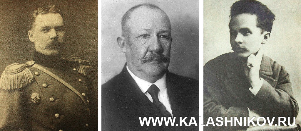
From left to right: V. G. Fedorov exercised supervisory control over the work on the creation of a machine gun in Tula; The general management of the design of the machine gun was entrusted to P. P. Tretyakov; I. A. Pastukhov is the direct executor of the work on the machine gun Photo of 1889 (VIMAIViVS)
The beginning of the process of creating a large-caliber machine gun dates back to October 27, 1925, when the Permanent Commission on Armament of the Red Army in the minutes of the meeting No 4/KV decided the following: “In view of the lack of a large-caliber anti-aircraft machine gun in service, to instruct the Artillery Committee, by May 1, 1927, to develop a sample of this machine gun and cartridges for it with a caliber of 12 to 20 mm. of the fight against tanks”.
Initially, it was planned to develop a 14 mm machine gun, but later settled on the 12.7 mm caliber, as the most common in other armies. The draft technical specifications (TU) for the large-caliber machine gun were developed by April 1926 (the development of the TU was carried out by the NTK UVVS) and already on May 17, the Artillery Committee of the GAU adopted a resolution on the design of the machine gun at the Tula Arms Plant. Having considered the task, the plant management decided to organize a special section of the design bureau to work on this particular project. The general management of the design of the new machine gun was entrusted to P. P. Tretyakov, who had previously been in charge of the machine gun department of TOZ. Personally, work on the machine gun was entrusted to I.A. Pastukhov (in the documents of the AUhe was called “senior designer - executor of special. work”), transferring him to a new position from the assembly and machine gun workshop. His group also included draftsmen I. P. Somov and S. A. Yartsev, who later became a famous weapons designer. The mount for the new machine gun was developed by designer S. A. Prilutsky. Supervisory control over all work in Tula on the part of the “RUJ Trust” was carried out by the engineer of the Kovrov Arms Plant (I.N.Z No 2), the famous gunsmith V.G. Fedorov.
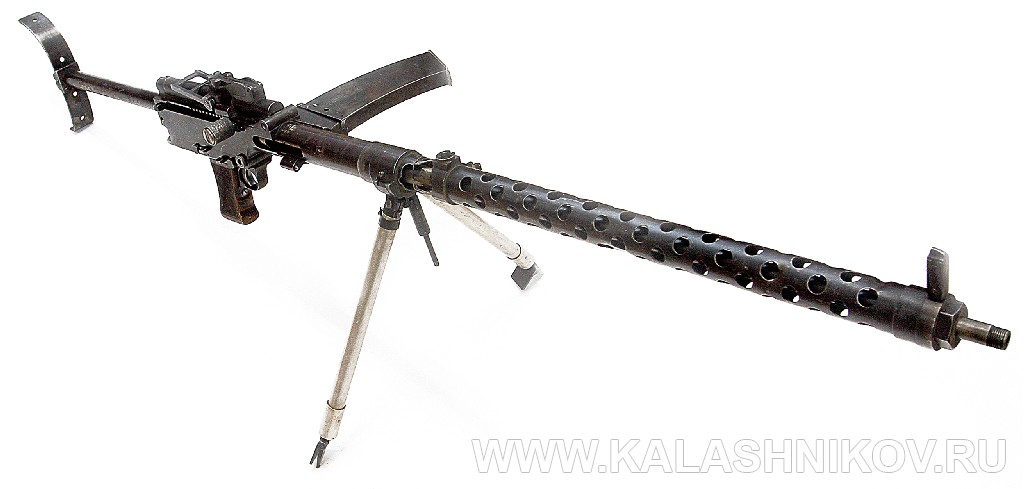
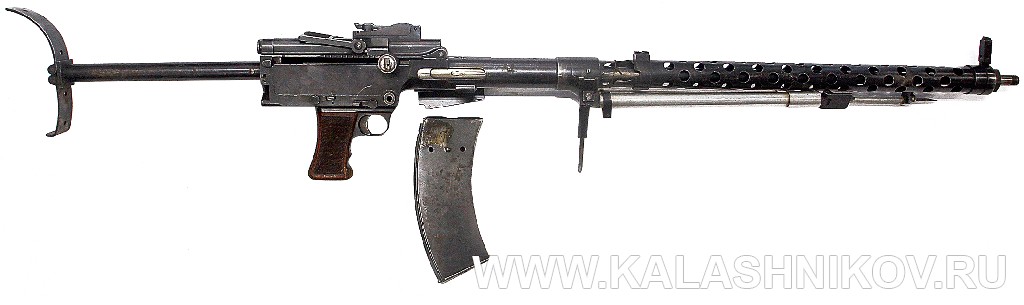
Общий вид 7,62-мм ручного пулемёта «Дрейзе» под патрон 7,62х53R
Тактико-технические требования к 5-лин. (12,7-мм) пулемёту (документ хранится в коллекции ВИМАИВиВС)
16 июля 1926 года журналом 5-й секции Арткома АУ № 525с от 17.05.1926 г. были оформлены окончательные технические условия (так тогда называли тактико-технические требования — ТТТ) к проектируемому оружию — пулемётам (ручному калибром 7,62 мм и тяжёлому — 12,7 мм), которые выслали потенциальным разработчикам. Перечень требований включал в себя следующие основные моменты:
— пулемёт предназначен для вооружения самолётов и для стрельбы в земных условиях;
— пулемёт должен быть спроектирован под 12,7-мм патрон, принятый в английской армии для крупнокалиберного пулемёта Виккерса;
— темп стрельбы для воздушного варианта пулемёта не менее 750 выстр./мин, для наземного не более 500 выстр./мин;
— вес сухопутного варианта пулемёта не более 25 кг, авиационного — не более 20 кг;
— конструкция пулемёта при замене приёмника должна допускать питание пулемёта патронами (ход ленты) как с правой, так и с левой стороны и не требовать введения дополнительных частей в конструкцию приёмника;
— охлаждение ствола воздушное.
Среди прочего к документу имелось дополнительное указание: «До получения образцов 5-линейного пулемёта принять пока в основу при проектировании пулемёт «Дрейзе». Почему именно этот пулемёт был указан в качестве образца? У Арткома АУ имелись довольно веские причины для такого решения. Дело в том, что работу по созданию крупнокалиберного пулемёта пришлось начинать с чистого листа — сколь-нибудь значимый опыт конструирования подобного автоматического оружия в СССР (да и в Императорской России) в то время отсутствовал. В этой ситуации, как это не раз бывало и раньше, и позже, молодой Советской республике пришлось опереться на зарубежный опыт. Одним из мероприятий являлась покупка лицензии на проверенную иностранную конструкцию — английский 12,7-мм пулемёт Виккерса. Осенью 1926 года этот пулемёт, оснащённый синхронизатором ПУЛ-9 разработки ТОЗа, испытывался на самолёте разведчике Р-1. Испытания прошли неудачно: стрельба из пулемёта вызывала деформацию обшивки и элеронов — самолёт-разведчик Р-1 оказался слаб для подобного оружия. Но с англичанами не удалось договориться о продаже лицензии на изготовление пулемёта и стало ясно, что придётся искать другие пути получения оружия данного типа. При этом полностью отказываться от использования иностранного опыта никто не собирался. Кроме англичан, техническую помощь СССР в разработке вооружений оказывала и тогдашняя Веймарская Германия.
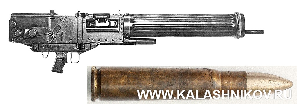
12,7-мм английский пулемёт «Виккерс» и патрон .50 Vickers (12,7х81) (патрон хранится в коллекции ВИМАИВиВС)
Основания для опоры на германские разработки имелись: в 1923 г. во время визита в Германию одной из советских военных делегаций среди разных новинок нашим специалистам показали ручной пулемёт «Дрейзе». Образец произвёл сильное впечатление: он был прост по устройству, компактен, лёгок и надёжен. «Дрейзе» (Dreyse) — это торговая марка фирмы Теодора Бергмана Bergmannindustriewerke. Прототип ручного пулемёта «Дрейзе» был разработан сотрудником этой фирмы Луисом Шмайссером ещё в 1915 году — это был лёгкий станковый пулемёт Бергмана М1915. Проигравшей Первую мировую войну Германии было запрещено разрабатывать новое оружие, но такие работы продолжались зарубежными филиалами немецких фирм и в самой Германии, и под видом модернизации ранее созданных конструкций. Упомянутый ручной пулемёт «Дрейзе» являлся продуктом тех самых, «полутайных» работ. Действие автоматики пулемёта основывалось на использовании отдачи ствола при его коротком ходе. Оригинальной была система запирания канала ствола. Массивный затвор, до момента выстрела сцеплялся со стволом при помощи двуплечего запирающего рычага, взаимодействующего своими концами с одной стороны с вырезом в затворе, а с другой — со специально спрофилированной поверхностью на затыльнике затворной коробки. После выстрела, когда ствол с затвором пройдут путь, достаточный для того, чтобы пуля покинула канал ствола, скос на затыльнике, взаимодействуя с задним плечом запирающего рычага, поворачивает его на незначительный угол вниз, выводя из зацепления с затвором. После этого вступает в действие ускорительный механизм, который увеличивает скорость отката затвора и тормозит откат ствола. Боевая пружина вынесена в ствольную коробку, что предохраняло её от перегрева и осадки (бывшего бичом конструкций Дегтярёва, где пружина помещалась под стволом), при этом общее число трущихся поверхностей получилось минимальным. У подобной компоновки запирающего механизма имелись и проблемные стороны: для изготовления запирающего рычага требовалась высококачественная сталь и довольно высокая точность обработки.
| Тип боеприпаса | 12,7х81 .50 Vickers (.5V/580)(Англия) | 13,2х92SR Mauser (Германия) | 13,2х99 Hotchkiss (Франция) | 12,7х99 (.50 BMG) (США) | 12,7х108 ДК (СССР) |
|---|---|---|---|---|---|
| Масса пули, г | 37,6 | 51,5 | 52,2 | 46 | 48 |
| Масса патрона, г | 83 | 119 | 119 | 110 | 134 |
| Начальная скорость, м/с | 775 | 785 | 800 | 858 | 840 |
| Дульная энергия, КДж | 11,3 | 15,9 | 16,6 | 16,8 | 16,2 |
К моменту прекращения сотрудничества СССР с фирмой «Виккерс» по крупнокалиберным пулемётам в 1926 г., взаимодействие советских военных с германской фирмой Bergmannindustriewerke находилось в самом разгаре. РККА нуждалась в современном ручном пулемёте, и пулемёт «Дрейзе» был признан наиболее подходящим для этой цели образцом. В сентябре 1925 г. станковый пулемёт Dreyse MG.15 прошёл испытания в СССР на опытном ружейно-стрелковом полигоне, где получил высокую оценку качества конструкции и боевых характеристик. К декабрю 1926 г. советская делегация закупила в Германии для проведения исследований ручные пулемёты «Дрейзе» в количестве 10 шт., а также станковый вариант, переделанный под советский 7,62-мм винтовочный патрон. Рассматривался даже вопрос введения пулемётов типа «Дрейзе» на вооружение РККА! Но дальнейшее сотрудничество с Германией в области стрелкового оружия застопорилось, из-за того, что немецкие фирмы поставили «совершенно неприемлемые» условия: в частности, стоимость пулемёта составляла 6000–10000 марок. Кроме того, на конкурсных испытаниях ручных пулемётов, прошедших в июне 1927 г., ручной пулемёт «Дрейзе» проиграл дегтярёвскому ДП, однако составив ему очень серьёзную конкуренцию. Указанные выше положительные свойства пулемётов «Дрейзе» и побудили советских военных выдать задание на разработку на его основе крупнокалиберного пулемёта — простого, лёгкого, пригодного к применению на земле и в авиации.
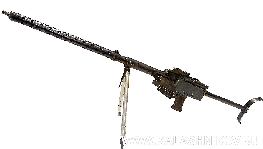
Пулемет «Дрейзе», вид слева
Здесь следует особо обратить внимание на то, что АУ видело вновь разрабатываемый пулемёт унифицированным образцом для армии и ВВС (причём для ВВС — одновременно в турельном и синхронном варианте), что должно было способствовать уменьшению количества образцов оружия принятых на вооружение, упростить снабжение войск запчастями и обучение пользователей. Возможно, упор на универсализацию стал следствием влияния английского подхода к этому виду оружия, ведь английский пулемёт .50 Vickers выпускался в сухопутной, морской и авиационной модификациях. По пути универсализации крупнокалиберных пулемётов пошли и в США. Можно предположить, что в случае успешной разработки в СССР крупнокалиберного пулемёта универсального типа, могло получиться семейство пулемётов, сходных с американским Browning М2НВ и его авиаверсией AN/М2. Но, что очень важно — советские военные хотели, чтобы при универсальности пулемёта некоторые его важные характеристики в воздушном и наземном вариантах существенно отличались друг от друга. Например, в ТТТ темп стрельбы для воздушного варианта задавался не менее 750 выстр./мин, а наземного — не более 500 выстр./минуту. При этом вес пулемётов обоих версий должен находиться в пределах 20–25 кг. Это весьма жёсткие требования для того времени! В принципе, приблизится к заданным требованиям по массе, при использовании патрона и ленты пулемёта Виккерса было возможно. Как стало известно значительно позднее, создание универсального оружия пригодного для использования в средах и на технике, существенно отличающимися по свойствам и тактике применения, является очень непростой задачей, и целесообразней создавать специализированные образцы. Однако в середине 1920 гг. это ещё не было очевидным, и советские военные — заказчики пулемёта вместе с его разработчиками пошли по самому трудному пути, что в итоге сказалось на судьбе изделия.

Слева приведена схема функционирования автоматики пулемёта «Дрейзе», рядом – схема функционирования ускорительного механизма этого пулемёта
Work on the design of a large-caliber machine gun began on August 3, 1926. It was implied that the design of the designed machine gun should be based on the basic diagram of the automation and main mechanisms of the German machine gun, but the design of the design details would be new and correspond to the TTT. As mentioned above, the machine gun was originally designed for the British .50 Vickers machine gun (12.7×81) and its belt. Why was this particular ammunition chosen, not the most effective in its class, inferior in power to its peers - the 13.2SRx92 Mauser cartridge for the TuF machine gun and the 12.7×99 cartridge for the Browning M1921 machine gun? The reason for this choice was quite prosaic: the USSR had a stock of such cartridges and belts (left over from an unsuccessful attempt to obtain a license for the .50 Vickers machine gun), which was considered sufficient to quickly launch design solutions, since the development of a domestic powerful 12.7 mm cartridge required a lot of time. In principle, the low power of the British cartridge could be tolerated: the effectiveness of firing at plywood and fabric aircraft of the 1920s, which did not have any protection even with such cartridges, was more than sufficient, and the armor-piercing cartridge coped well with the armor of the then mainly light tanks, designed to fire armor-piercing bullets of 7.62 mm caliber. that tanks and aircraft would not receive enhanced protection in the near future. Therefore, soon after the start of work on the creation of a large-caliber machine gun, the AU decided to begin work on the creation of a domestic cartridge of increased power for it.
Dreyze machine gun, right view,
bipod folded, magazine separated. The bipod was folded towards the muzzle
As mentioned above, the large-caliber machine gun (in the documents of the TOZ and the Autonomous Institution of the Red Army, it was called the 5.P machine gun, i.e. a 5-line machine gun) should be ready by May 1, 1927, but the work was significantly behind schedule: in July-August 1927, two firing prototypes of the machine gun were manufactured. However, they did not succeed in firing bursts - machine guns fired only single shots. A properly functioning and testable machine gun was ready only in May of the following year, 1928. One of the difficulties that seriously hampered the development of the 5.P machine gun was the shortage of 12.7 mm British cartridges. Their supply was limited, and the AU demanded that the plant economically consume the allocated ammunition and strictly report for it. Therefore, weapons were tested with a very small number of shots.
While studying at the Penza Artillery Engineering School, when work began on my graduation project, I found it interesting to develop a project of a rifle for law enforcement units, as compact as possible, for a large-caliber cartridge like a revolver. I will leave aside the justification of the expediency of the idea of such a weapon - of course, it existed, but it is not about it, and the graduation project is not developed in order to revolutionize military affairs, but is needed to assess the quality of the cadet’s training.
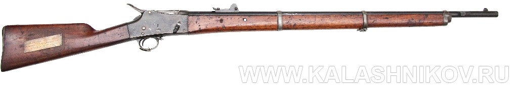
Krag-Petersen rifle (sample from the collection of VIMAIViVS)
Locking mechanism of the Krag-Petersen rifle. The gate is lowered to the feed line
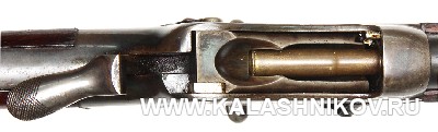
The bolt is on the ramming line, there is a cartridge on the bolt tray
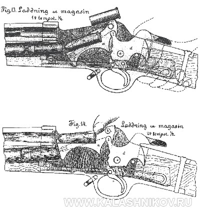
Diagram of the Krag-Petersen rifle, from top to bottom: 1 – the bolt is open, the case is reflected, the new cartridge is on the bolt receiving tray; 2 – the bolt is raised to the ramming line, the new cartridge is on the bolt receiving tray and is sent into the chamber with the shooter’s finger
I began to “figure out” how to design the mechanisms, and decided that it would be optimal to use a Peabody-type oscillating bolt, an underbarrel tubular magazine and reloading with a movable forearm. Such an unusual combination of main mechanisms, in my opinion, made it possible to ensure the compactness of the receiver and reduce the dimensions of the weapon as a whole, as well as to do without complex locking mechanisms. In those years, it was not yet possible to search for analogue samples using the Internet, there was also not much foreign weapons literature, so they had to rely exclusively on the analysis of domestic “paper” sources. A search in the book by V. E. Markevich “Hand-held Firearms” showed the presence of only one rifle with an oscillating bolt and an underbarrel tubular magazine - it was just a Krag-Petersen rifle. But according to the diagrams of the device found in this book, it was not clear - how in this rifle the cartridge is sent from the bolt tray to the chamber? I decided that the cartridge ramming mechanism was simply not shown on the diagram. This means that you will have to invent it yourself. Having drawn a lot of paper with sketches of options for solving the rifle mechanisms, it was possible to come up with a kind of lever ramming mechanism, powered by the rod of the movable forearm. To hold the cartridge on the bolt tray when moving the cartridge from the magazine, I used a hinged spring-loaded cover. I decided to squeeze the cartridges in the magazine from the bolt when it was lifted with a special swinging lever. The cartridge was to be rammed into the chamber and the barrel bore locked in one forward movement of the forearm, during which the bolt made two movements: the first stroke was lifting from the feed line with the cartridge on the tray, stopping at the ramming line and ramming the cartridge into the chamber, the second stroke was lifting the bolt with closing and locking the barrel bore.
He drew sketches of the parts and assemblies of the rifle, made a working model of it from available simple materials (plexiglass, tin, nails, plywood, aluminum ski poles). He made replicas of cartridges from scraps of rifle cases. I assembled the product. And it worked! The model was loaded with cartridges, they were sent into the chamber, the cartridges were removed and reliably thrown out of the weapon. The defense of the project went with a bang, the teachers, of course, were impressed by the demonstration part with a demonstration of the model.